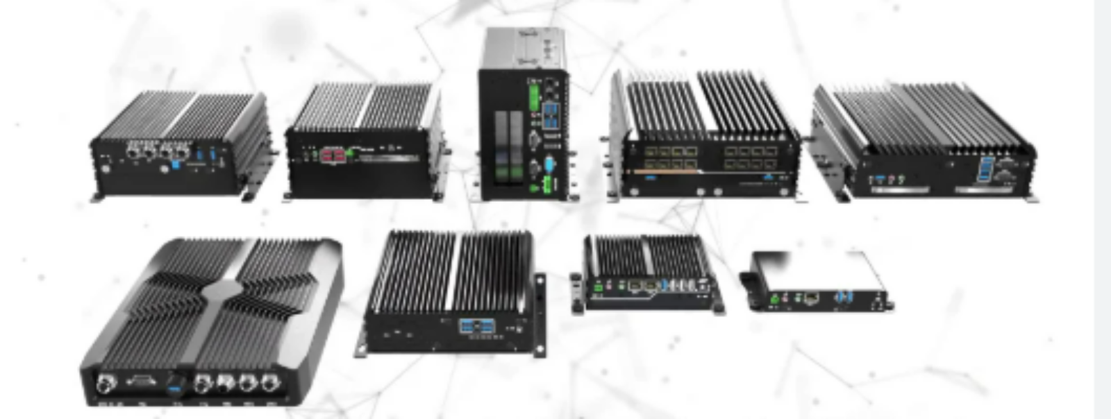
A panel PC enclosure is one of the most demanding products in industrial electronics packaging. It has to hold a touchscreen perfectly flat, seal the electronics behind it against dust and water, dissipate heat without fans, and survive years of wiping, washdown, or vibration — all while looking clean enough for an operator to touch eight hours a day. Getting all of that right is less about buying a stock box and more about making a sequence of engineering decisions early. In this guide we walk through how a custom panel PC enclosure is actually engineered and built, based on the questions OEM teams ask us most often at YW-TECH.
Sealing Strategy: IP65, IP66, and IP69K Are Different Problems
The most common misconception we see is treating all ingress protection ratings as one ladder where “higher is just better.” In practice, an IP65 enclosure that passes dust-and-jet testing can fail a washdown environment, because IP69K adds high-temperature, high-pressure water at close range — and that changes the gasket design fundamentally.
For a standard IP65 front panel, a continuous silicone or EPDM gasket compressed 20–30% around the bezel, retained in a machined or rolled groove, is usually sufficient. The critical details are corner continuity and screw spacing: at anything wider than roughly 100 mm between fasteners, the bezel can bow under gasket load and create a micro-leak path right at the touchscreen edge.
For food and beverage, pharmaceutical cleanrooms, or outdoor HMI cabinets exposed to pressure washing, we move to IP66 or IP69K construction. That typically means:
- A 304 or, for aggressive caustic/salt environments, 316L stainless steel bezel with a smooth, crevice-free weld on the rear housing.
- A food-compatible FDA-grade silicone gasket profile sized specifically for the washdown pressure, not reused from a generic seal kit.
- Cable entries moved to the bottom with sealed M16/M20 glands or conduit fittings, so water never pools on top of an entry point.
- No recessed screws or unsealed labels on the front face — everything flush, laser-etched, or relocated rearward.
Compliance is verified against IEC 60529 test methods, and for washdown machines we also pay attention to hygiene design guidance such as EN 1672-2 so the enclosure has no horizontal ledges where product residue can collect.
Thermal Design: Making Fanless Actually Work
Most industrial panel PCs are specified fanless, and the enclosure is where fanless design succeeds or fails. The heat path we design around is straightforward: CPU → heat spreader or heat pipes → enclosure rear wall → ambient air. What matters is engineering that rear wall as a heat sink rather than a barrier.
Depending on the TDP of the compute module — anywhere from a 10 W ARM module to a 65 W desktop-class edge AI board — we use different tactics:
- Internal spreaders and heat pipes to move heat from a concentrated die to a larger wall area.
- Finned or extruded rear panels to increase surface area, often in 6063-T5 aluminum with anodizing to improve emissivity.
- Thermal simulation (CFD) during DFM review to predict internal air temperature before the first prototype is cut, so we are not iterating through three tooling rounds to find a hotspot.
A useful rule of thumb: if the internal air temperature stays below roughly 45–50 °C, most industrial-grade components hold their specified lifetime. Above that, electrolytic capacitors and display backlight drivers start aging much faster. We design the enclosure to hit that budget at the customer’s stated maximum ambient, not at a datasheet-friendly 25 °C.
Materials, Tolerances, and the Front Bezel Problem
The front bezel is the hardest single part of a panel PC enclosure. It carries the touchscreen cutout — typically held to ±0.1–0.2 mm so the display gasket seats correctly and the touch frame is not stressed — plus mounting bosses, status LED pipes, and sometimes an RFID or emergency-stop aperture. That mix of cosmetic surface and tight cutout tolerances is why we typically combine processes:
- CNC machining for the bezel and critical cutouts.
- Laser cutting and CNC bending for the rear housing in 1.5–2.5 mm sheet, usually 5052 aluminum or 304 stainless steel.
- TIG welding with grinding and polishing on visible seams of stainless housings.
- Powder coating (polyester or epoxy-polyester) on aluminum parts, with masking of grounding and gasket surfaces; stainless is usually passivated instead.
Vibration matters too. For vehicle-mounted or machine-mounted HMIs we design mounting flanges and bracket interfaces referencing MIL-STD-810 style vibration profiles so the enclosure does not transmit panel-induced resonance into the display connector area.
From Prototype to Low-Volume Production
Panel PC programs rarely start at 10,000 units a month. More often an OEM needs 50–500 units per quarter across several SKUs — different screen sizes, different mounting, regional variations. That is exactly the low-volume, high-mix work we are set up for: laser cutting and CNC mean no hard tooling, so design revisions cost days rather than a tooling change order. A typical flow for us is DFM feedback within a few days of receiving CAD, first prototypes in two to three weeks, then a stable repeat-order process with consistent material traceability.
If you are evaluating suppliers for a custom panel PC enclosure — whether it is a sealed IP69K washdown HMI or a fanless edge AI terminal — the fastest way to de-risk the project is to bring the thermal and sealing requirements into the conversation at the enclosure design stage, not after the electronics are frozen. You can review our full range of capabilities on our what we can do page, read more about sealed designs in our rugged enclosure design guide, see how fabrication choices compare in our sheet metal enclosure fabrication guide, and when you have drawings ready, contact us for a DFM review and quotation.