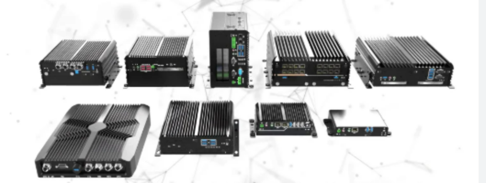
A data center chassis solution is far more than a sheet-metal box that holds a server. It is a balanced thermal, mechanical and electromagnetic system that decides whether a rackmount platform runs cool, stays within its acoustic budget and survives years of continuous duty. As compute density climbs and 1U and 2U nodes pack more cores, accelerators and NVMe drives into the same footprint, the enclosure has become a limiting factor in reliable operation. A well-designed chassis directs air exactly where it is needed, protects sensitive electronics from interference, and lets a technician swap a failed part in minutes instead of hours. At YW-TECH we design and fabricate custom data center chassis solutions around these three priorities — thermal performance, serviceability and electromagnetic integrity — then build them in low-volume, high-mix runs for OEM and ODM customers.
The Chassis Is Part of the Cooling System
The single most common failure in rackmount design is treating cooling as something the fan does alone. In practice, the chassis defines the air path. Cold air enters at the front, passes over VRMs, memory and drives, and exits at the rear through the power supply and fan wall. Any obstruction, sharp bend or unsealed gap along that path lets hot air recirculate back to the intake — a phenomenon that can raise inlet temperatures by several degrees even when the fans are running at full speed.
A proper data center chassis solution starts with a clear, front-to-back airflow channel. We model the internal volume, keep cable bundles out of the airstream with dedicated routing channels, and use blanking panels and gasketed drive bays so air cannot bypass the components that need it. Perforated front bezels are tuned for open area: enough to feed the fans without starving them, while maintaining the structural rigidity a shipping chassis needs. When airflow is designed in from the first sketch, the result is lower fan RPM, lower acoustic noise and a smaller thermal margin to worry about.
Choosing the Right Form Factor: 1U, 2U, 4U and Beyond
Form factor sets the rules of the game before a single component is placed.
- 1U chassis pack maximum rack density but leave very little vertical room for heatsinks or large fans. They demand careful component selection, high-static-pressure fans and often a custom cold plate for high-TDP CPUs.
- 2U chassis are the workhorse of the data center. The extra height allows taller heatsinks, redundant hot-swap fan modules and more drive bays, which is why most general-purpose servers and storage nodes land here.
- 4U and taller chassis suit GPU-dense compute, high-end storage and systems that need multiple power supplies or internal expansion cards. They offer the most thermal headroom and the easiest service access.
Because we fabricate rather than resell catalog enclosures, YW-TECH can adjust the internal board mounts, drive cages and fan walls to the exact form factor your program needs — including non-standard depths for edge or telecom racks. Our earlier engineering note on rackmountable form-factor chassis for data centers explores how these geometry choices affect density and service access in more detail.
Airflow Components: Hot-Swap Fans and Filtered Intake
A data center chassis solution intended for production duty should assume that a fan will eventually fail. Hot-swappable fan modules let a technician replace a failed unit without powering down the node, protecting uptime in a way that a fixed-fan design cannot. We design fan walls with keyed connectors, tool-less latches and per-fan status sensing so the enclosure supports the monitoring firmware rather than fighting it.
Filtered intake is the other half of the story. In dusty or industrial-adjacent sites, a washable or replaceable intake filter keeps particulate out of the server while maintaining acceptable pressure drop. The filter medium and its surface area must be matched to the fan curve — an undersized filter quietly throttles airflow and undoes all the thermal work done upstream. We specify the filter together with the fan selection, not as an afterthought, and validate the assembled chassis with temperature and airflow measurements on the prototype.
Power, Cable Management and Serviceability
Good cable management is a thermal feature as much as a neatness feature. Unmanaged cabling across the front intake is one of the fastest ways to create hot spots in a 1U or 2U server. We build in routing channels, tie-down points and staggered connector positions so power and signal harnesses stay clear of the cooling path and remain accessible when the lid is opened.
Power distribution is planned at the same time. Whether the design uses a single PSU, redundant hot-swap supplies or a DC bus input, the chassis must provide the right cut-outs, grounding continuity and strain relief. Serviceability extends to the small details: captive screws that cannot be dropped into a live rack, clear internal labeling, tool-less drive trays and lid designs that do not require removing the whole unit from the rack for routine maintenance. These choices reduce mean time to repair and are exactly what separates a production data center chassis solution from a prototype-grade box.
Material Selection and Fabrication
The base metal determines strength, weight, corrosion resistance and cost. Common choices include:
| Material | Typical use in a data center chassis | Why it is chosen |
|---|---|---|
| SPCC cold-rolled steel | Main chassis body, 1U/2U frames | High strength, low cost, good formability |
| SECC / galvanized steel | Structural panels in humid or coastal sites | Added corrosion resistance at modest cost |
| 5052 / 6061 aluminum | Lids, fronts, lightweight and thermal-sensitive builds | Light, corrosion resistant, good conductivity |
| Stainless steel 304/316 | Harsh or washdown environments | Maximum corrosion resistance and strength |
Our fabrication chain — fiber laser cutting at ±0.05 mm, CNC punching and machining at ±0.02 mm, press braking to ±0.1 mm, and TIG/MIG/spot welding — holds the tight seams that rackmount rails and drive cages depend on. Finishes such as powder coating, zinc-nickel plating and conductive anodizing are selected to suit both the environment and the electrical-grounding scheme. Because we run low-volume, high-mix production, these process choices can be tailored per program rather than frozen around a single catalog SKU.
EMI/RFI Shielding for Dense Electronics
High-speed SerDes links, switching power supplies and dense accelerator cards make modern servers significant emitters, and they are equally susceptible to outside noise. An EMI/RFI shielded enclosure for a data center chassis combines conductive seams, filtered I/O panels and honeycomb vents that pass cooling air while reflecting RF energy. Grounding points must be deliberate — paint under a grounding lug or gasket is a classic source of intermittent compliance failures.
When a program must meet FCC Part 15, CISPR 32 or a stricter internal EMC limit, it pays to design the shielding in from the start. Our engineering guide on EMI/RFI shielded enclosures covers the gasket, vent and plating choices that make a chassis compliant without compromising airflow — a balance that matters especially in high-density rackmount systems.
From Edge to Core: One Enclosure Philosophy
The line between a data center chassis and a rugged edge cabinet is blurring. Edge nodes sit closer to the source of data — in factories, base stations and retail sites — where temperature swings, vibration and limited rack infrastructure are common. The same discipline of directed airflow, filtered intake and serviceable fan modules applies, but the enclosure may need a higher ingress rating and a wider operating temperature range. Teams deploying both core and edge platforms often benefit from a single supplier who can carry the same design language across both. Our guide to rugged edge computing cabinets shows how these requirements translate into outdoor and 5G-ready builds.
Specification Window
| Parameter | Typical range / option |
|---|---|
| Form factors | 1U, 2U, 3U, 4U; custom depths for edge/telecom racks |
| Materials | SPCC, SECC/galvanized steel, 5052/6061 aluminum, SS 304/316 |
| Cooling | Front-to-back airflow, hot-swap fan walls, filtered intake |
| Finishes | Powder coat, zinc-nickel, electroless nickel, conductive anodize |
| EMI/RFI | Conductive gaskets, honeycomb vents, filtered I/O, 40–100 dB options |
| Tolerances | Laser ±0.05 mm, CNC ±0.02 mm, bend ±0.1 mm |
| Production | Rapid prototypes through low-volume, high-mix OEM/ODM runs |
Talk to a Fabricator Early
The best time to shape a data center chassis solution is while the board layout and component selection are still flexible. Tell us your form factor, processor and accelerator thermal envelope, drive count, airflow direction, I/O layout and any EMC standard you must meet. We will return DFM feedback, a practical fabrication route and a tested prototype before you commit to production tooling. Review the full range of our capabilities on our services overview, and when you are ready, request a quote for a custom data center chassis — a drawing or even a sketch is enough to start the conversation about lead time and cost.